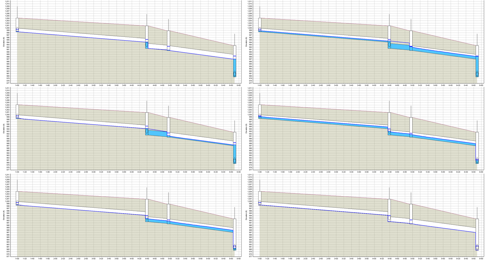
Here’s a short comparison of how the hydraulic grade line (HGL) of a 1-Dimensional model varies when using the Kinematic Wave routing method vs. the Hydrodynamic routing method. I used Autodesk Storm and Sanitary Analysis and this model shows a set of pipes in a system I designed a year ago in Georgia. The first clip shows the kinematic wave method and the second one shows the hydrodynamic method.

Kinematic Wave
The kinematic wave method is a non-linear reservoir formulation that assumes the water surface is parallel to the invert slope. This method solves the continuity equation and a simplified form of the momentum equation for each conduit. Advantages to this method include: faster simulation time due to the simplified nature of its equations, and ability to maintain numerical stability with large time steps (5-15 minutes), which is advantageous in long term simulations. Some of the limitations of this method: it cannot simulate backwater or reverse flow, simulate conduits with negative slopes, as well as pressurized flow (in which case, the Hazen-Williams or Darcy-Weisbach equations are used).
Hydrodynamic
The hydrodynamic method solves the complete Saint-Venant equations (continuity and momentum equations in conduits and a volume continuity equation for nodes). Advantages of this method include ability to model various types of flow that cannot be modeled with the kinematic wave method, as well as providing more accurate results (theoretically). Some disadvantages include the necessity for much lower time steps (<1 min.) which can result in a longer simulation time.
How do they compare?
As with any simplified method, the kinematic wave method tends to produce more conservative results. Pipes often surcharge faster as the maximum flow rate is determined by Manning’s equation for normal flow, which is a bit lower than the actual maximum flow in a pipe (more on that in a future post). The simulation time is much quicker than the hydrodynamic wave. HGL’s are computed between the upstream HGL and downstream HGL and interpolated between the US and DS nodes. The hydrodynamic wave method shows a more “realistic” HGL (as realistic as a 1-D model will allow). Simulation time is slower but the results show HGL’s with more accuracy, allowing for better assessment of inlet structure and pipe capacities.
Which is the preferred method?
Without a doubt, the hydrodynamic method is the preferred method I use when designing systems. The only exceptions are when a client specifies the use of the kinematic wave method or steady flow computations particularly to provide the most conservative results. I previously worked for an employer who did municipality-wide assessments of stormwater systems, and so we would find ourselves running simulations for networks with thousands of interconnected pipes and open channels. In these cases, the kinematic wave method was the preferred method as it sped up computation time significantly, and in the consulting world, time is money. It seems that, for the time being, as 1-D simulations are still preferred by most of the municipalities and clients that employ me, and therefore, I would use these methods in the following situations:
- Kinematic wave if it is requested by the client, or if I’m running simulations of large systems (500+ conduits) to check for pipe capacity. Additionally, if I am designing a system in a flood-prone area where surcharges are common, I’d prefer to use this conservative method as it can account for pressurization caused by sudden flow increases in pipes.
- Hydrodynamic wave for all other situations and when accurate HGL’s are necessary for inlet surcharge determination.
